Deep Drawing & Ironing
There are already numerous publications on the subject of the process combination of deep drawing and ironing and on the importance of this process in modern production technology. As a recognized expert in this field, I would like to comprehensively present both the theoretical aspects and the practical application of these techniques in a series of articles.
One of the first patents in the field of deep drawing and ironing was issued in the USA in 1904 (Rigby Patent No. 760, 921). Nevertheless, the process was already widely used for the production of cartridge cases before this date.
Despite its long history, the technology of deep-drawing combined with ironing and its commercial application is nowadays within a relatively small group of companies. A possible reason for this could be the skepticism towards this process. It is hoped that a detailed explanation can help overcome this skepticism and provide a better understanding of this straightforward engineering technique.
In this overview, the author aims to appeal to both the academic reader and the manager of a pressing plant.59
The Process
Ironing is typically performed on a straight-sided cylindrical can, which can be made from a flat preform by deep drawing, forging , or extrusion. Flow forming a cylindrical preform is also a common method. However, in this article we will focus on fabrication from a circular flat preform, which is always of greater thickness than the final wall thickness. This may seem obvious, but it is important to emphasize this detail as it can have both advantages and disadvantages.
For example, when a design requires a particular thickness at the base, such as with cartridge cases or beverage cans, the thick preform is an advantage because the base thickness then matches the thickness of the preform. In other applications such as liquid or gas containers such as camping cylinders where an elliptical or hemispherical end shape is required, there is no need for excess metal at the ends of the container. In such cases, a thick preform would be rather disadvantageous.
When using a thicker sheet metal, the need for a blank holder should be questioned. However, often no blank holder is required, which can be determined by a simple estimation, as we will discuss later in the theoretical part of this article.
When working with a disc, the preform is positioned at the opening point of a tractrix drawing die and is centered with respect to the axis of the drawing die. Precise positioning is particularly important with Tractrix drawing dies to prevent an uneven height of the frame. Because no centering is used, the preform must flow evenly into the drawing die to create a regular shape.
During the process, the preform will thicken as it assumes a cup shape. A "corrective" ironing is often incorporated into the Tractrix drawing die , producing a uniform wall thickness that matches the thickness of the original preform. The radial stresses applied to the drawing die must be calculated and the repeated radial stress should be considered in terms of fatigue life. In certain cases it may be necessary to construct a drawing die with reinforcement.
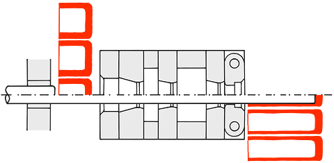
If the process does not start from a disc but from a cylindrical preform , the cup is positioned in a center and the punch advances and performs the movement in a guidebush. This process is shown in Figure 1. The workpiece is placed in a sinking die , which reduces the component to the diameter of the punch. Once this is achieved, the ironing is carried out as previously described.
The process typically requires long stroke hydraulic presses and specially designed machines with the appropriate characteristics are available. Both horizontal and vertical presses can be used, but a new generation of horizontal machines has entered the market. These presses use both the forward and return strokes effectively. A more detailed description of these machines follows in a later part of this series of articles.
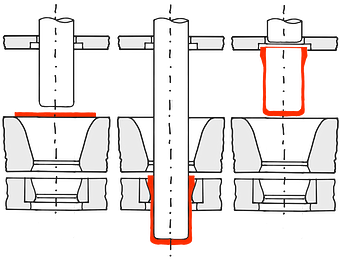
The ironing process can be interrupted before the workpiece is fully fed through the final drawing die. The component is then withdrawn and released from the punch using a stripper plate as shown in Figure 2. In this way, a thickened end section can be produced, with the thickening being directed outwards.

A punch with a change in diameter at either the base or frame end can also be used as shown in Figure 3. This enables the inner walls of the component to be thickened at different points.
The process can be carried out very quickly if necessary. In such cases, mechanical presses are usually used. When producing beverage cans made of aluminum or tinplate, speeds of 150 to 180 strokes per minute can be achieved with a single stamping press. There are also machines that can use two punch at the same time. This method enables high-speed production of cartridge or bullet casings.
The process of deep drawing and ironing is characterized by the use of low forces and long strokes. This feature should be compared to reverse extrusion from a billet or bar , which uses high forces and short travel distances. However, in both cases the area under the working curve will be approximately the same.
The stamping force acts on the bottom of the drawn part, which leads to tensile stresses in the frame. If these tensile stresses reach the tensile strength of the material, there is a risk that the component will break. With a good understanding of the fairly simple mathematics involved, over stressing the frame of the component can be avoided.
Without this understanding, it is common to view a 30% reduction in wall thickness as significant and to perform a heat treatment after this amount of ironing. In traditional industries, such as cartridge case production, it is common to anneal 70/30 brass after about 30% reduction. However, it is quite possible to achieve a reduction of 70% to 80% without intermediate annealing.
The work hardening of the frame that occurs during heavy ironing must be taken into account as it influences the final ductility of the component.
Hot and hot forming
The previous description of the process is based on performing it at room temperature. However, deep drawing and ironing can also be carried out at elevated temperatures of up to around 750°C (hot forming for ferrous metals) and up to 1200°C (hot forming).
Normally, a billet or a bar is used as the starting material at higher temperatures because the forces required are significantly lower at these temperatures. The increased temperatures reduce work hardening and larger drawing ratios are possible.
At high temperatures, lubrication and tool wear can become problems. Additionally, the surface quality and accuracy of manufactured parts can be superior when working at room temperature. It is possible to achieve 70% to 80% of metal deformation by ironing at elevated temperatures. The process can then be continued at room temperature to achieve the remaining 20% to 30% deformation , improving the surface quality and accuracy of the component.
The pulling forces at high temperatures can be calculated similarly to those at room temperature. However, it should be taken into account that the yield stress of the material and the friction characteristics will be different at elevated temperatures.
theoretical aspects
The theoretical aspects of deep drawing and ironing are not only important but also well documented. The theory of plastic flow of metals has long been the subject of study and the behavior of metals during deformation has been largely explained.
The theoretical understanding and the various mathematical formulas developed help to explain the operations within the tool set and are in good agreement with measured loads and other practical factors. However, theory is generally only applied after the practical event.
Of course there are exceptions. Companies such as Liebergeld, Sieber and Schuler in Germany, Nobs in Switzerland, Nords Industries, Continental Can and American Can in the US and Metal Box in the UK to name a few all have extensive knowledge of the theory of the process. However, many other companies do not. These companies often emphasize that they are getting on with their work and are successful, and it can be said that the experienced professionals in these companies can say from experience what is feasible.
The author accepts this point of view, but emphasizes that this is only one side of the coin. Today, many things are possible in the press shop that experienced professionals find impossible, for example, ironing in more than one drawing die at a time.
Another example of a common belief is the claim that it is impossible to ironing in more than one drawing die at a time. This belief is widely held, although wrong, and it is often difficult to convince people that a multiple system of drawing dies works.
Those who rely on "trial and error" are likely to form the backbone of the sheet metal forming industry and represent an important base of experience that must be respected. But times are changing, and with the further development of lubricants, tool materials, raw materials and equipment, the press shops also have to adapt and expand their knowledge.
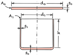
A fundamental consideration in deep drawing and ironing is the amount of reduction that occurs when converting a flat disk into a cup. It is common to consider diameter reduction, or the ratio of the diameter of the disc to the diameter of the punch, as an important parameter. But it is more accurate to calculate the ratio of the peripheral area of the blank compared to the peripheral area of the frame. This is an interesting and simple calculation which, while introducing error for thick blanks, is considered sufficiently accurate for thin blanks.
| Compression | εK | = | % |
| Draw ratio | βges | = | ||||
| Clear Height | h | = | mm | |||
| Diameter punch | d1 | = | mm |
In this context, the compression experienced by the metal plays a crucial role and is independent of original parameters such as the diameter or thickness of the blank and the final wall thickness. As an example, we assume that the draw ratio is βtot = 2.2 and we want to produce a drawn part with a length-to-diameter ratio of 3:1. In this case, the compression is 85.45%.
If we increase the draw ratio to 2.4 - which is certainly possible if we use a properly designed tractrix drawing die - the compression drops to 83.47%. From experience we know that 83.5% compression is feasible in one pass (with multiple stretching), while 85.45% is more difficult to achieve. Therefore, the choice of draw ratio is extremely important.
Let's take as an example the manufacture of a cylinder where a disc is converted into a drawn part where the barrel edge is compressed by 50%. Let's further assume that the next ironing drawing die in the sequence performs a 30% reduction and the following ironing drawing die also performs a 30% reduction. Then we know that the compression εK is given by:
(1-εK ) = (1-0.5) (1-0.3) (1-0.3)
This meansεK = 75.5%. This shows how the different stages of reduction in ironing contribute to an overall reduction of the metal.
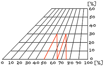
This can be determined graphically from Figure 5. Starting with 50% reduction on the horizontal axis, follow the sloping line to the point where the 30% reduction line on the horizontal axis is reached. At this point, go down vertically to a 65% reduction on the horizontal axis. From this point, follow the sloping line again until you reach the 30% reduction again, then go straight down again. The end result is an overall reduction of 75.5%, read off the horizontal axis.
This example demonstrates how sequential metal forming, specifically deep drawing and ironing, results in cumulative compression of the metal. It also highlights the importance of precisely controlling the reduction stages at each stage of the process to achieve the desired end result.
This process can be repeated as many times as required depending on the number of drawing dies used. Particularly in the case of very extensive ironing, it becomes clear that the transition from 90% to 95% total reduction requires at least one additional drawing die , or even more, in order to enable a further 50% compression. The key point is that the area of the cylinder walls is continuously decreasing. Therefore, a 50% reduction of an already reduced cross-sectional wall compared to the original peripheral area of the blank represents only a small overall reduction.
Deep drawing force
Calculating the punching force is crucial when deep drawing and ironing. The maximum force is achieved during the deep-drawing phase and when Tractrix deep-drawing tools are used without blank holders, the deep-drawing force corresponds to approximately half of the tearing force. For safety reasons, it is recommended to use a factor of 0.6 times the tearing force F,for example as a deep-drawing force to accept.
Although this calculation is simple, it is often found that there is a lack of a true understanding of force determination methods. Similarly, reverse extrusion forces are very easy to calculate, but are rarely applied in the shop. A situation then arises of using a press that is significantly oversized for the job, which is wasteful, or attempts to use the press on machines that are not powerful enough for the job.
There are, of course, numerous practical considerations. Large presses could be used because they are idle, and small presses could be used for the same reason while being heavily loaded. Nonetheless, the author believes that all stakeholders should strive to bridge the gap between the accomplished practitioner and the experienced theorist.
The ironing dies can be arranged so that two drawing dies are in action at the same time. In this case, however, the pressing forces do not simply add up, but are significantly lower, based on empirical observations.
The individual forces are calculated assuming room temperature conditions. However, the sheet metal heats up during the deep drawing process and becomes hot during the ironing sequence. This heating moderates the work hardening properties of the steel and mainly explains the observed reduction in total punching load.
Requirements for a blank holder
When considering a thick, rigid blank, it may itself have enough strength to withstand the tangential compressive stresses created during the drawing process. In this case no blank holder is necessary and the material can be drawn through a Tractrix drawing die.
However, if the sheet thickness is too small in relation to its diameter, deep drawing in a Drawing die die without a blank holder becomes impossible.
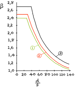
A look at Figure 6 shows where instability occurs when no blank holder is used. This instability manifests itself in the formation of wrinkles or warping of the blank. This instability depends on three factors: blank diameter, punch diameter and blank thickness. This reasoning is purely arithmetic in nature and is based on a flat punch pulling through a tractrix drawing die.
In many cases, the draw ratio or thickness of the blank is so "safe" that the holder can easily be dispensed with. This applies, for example, to the production of drawn and wall-drawn beverage or aerosol cans, where blanks that are usually 0.3 mm thick are used and a blank holder is necessary to avoid warping.
As a simple example: If a 0.3 mm thick billet is used with a draw ratio of (let's say) 2:1, a blank holder can be dispensed with as long as only a maximum punch diameter of around 10 mm is used.
However, there are other aspects to consider when assessing a blank's tendency to warp or wrinkle. If a billet is neither safe nor unsafe, other factors should be considered. The shape of the stamp base can also have a significant influence on the tendency to wrinkle, as can the quality of the blank edge and the hardness of the blank.
When a billet is close to a state where it deforms, it may or may not deform every time, depending on the hardness of the blank. When manufacturing a fire extinguisher body from extra deep-drawable steel, it was found that a hardness of less than 100HV resulted in wrinkles, while a batch of steel with a hardness of more than 120HV did not produce wrinkles.
It was also found that "drawing at the boundary" with a standard geometry Tractrix die mold resulted in wrinkling. However, when the die profile was modified to account for thickening and elongation of the blank, the wrinkle problems were immediately resolved.
This is where the art of metal forming surpasses theoretical predictions and is an area of the
Combination with the multiple drawing
So far, only single drawing processes that enable a maximum length-to-diameter ratio of 3:1 have been considered.
However, when this cylinder is retightened on a second punch by multiple drawing , additional untempered metal is drawn from the soft base of the component into the side walls. Without intermediate annealing, the redrawing ratio (1st punch + 2nd punch) can reach a maximum value of around 1.4:1. This increases the finished height-to-diameter ratio to approximately 4:1.
However, if intermediate annealing is performed, the redraw ratio can be increased to about 1.6, resulting in a maximum length-to-diameter ratio of about 9:1.
Verfahrenskombination | h/d |
|---|---|
1 x Tiefziehen & Abstreckgleitziehen | 3 / 1 |
2 x Tiefziehen & Abstreckgleitziehen | 4 / 1 |
3 x Tiefziehen & Abstreckgleitziehen | 5 / 1 |
2 x Tiefziehen & Glühen & Abstreckgleitziehen | 9 / 1 |
Tbl. 1 Height to diameter ratio | |