Drawing force on the straight drawn part side
7.1
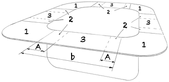
Fig. 1
Deformation zones during prismatic deep drawing
1 Corner area 2 Transition zone 3 Straight drawn part side A Length of transition zone b Straight drawn part side
U-bending is used to calculate the drawing force on the straight sides of the drawn parts. In combination with the friction forces on the blankholder and the length of the bending edge b, the drawing force can be calculated: 35
Eqn. 1
Eqn. 2
| Drawing force on the straight side | FZg | = | kN | ||
| Tensile stress | σZ | = | MPa |
| Coefficient of friction | μN | = | ||||
| Blankholderforce | FN | = | kN | |||
| Friction drawring | μZ | = | ||||
| Maximum Tensile Strength | Rm max | = | MPa | |||
| Length | b | = | mm | |||
| Sheet thickness | s0 | = | mm | |||
| Die radius | rM | = | mm | |||
| Punch radius | rSt | = | mm |
Calc 1
Drawing force straight side 35
35
Strackerjahn, W. / Die Voraussage des Versagensfalls beim Tiefziehen rechteckiger Teile / Dissertation / Hannover / 1982 / …