Prismatic drawn part
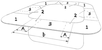
When deep drawing rectangular drawn parts, certain areas or zones can be identified, which are each subject to different shape change processes. These areas are:
Corner area
Sheet metal forming can be particularly complex in the corners of the drawn part. This is because the material in this area tends to move in different directions, which can cause excessive elongation and potentially cracks or wrinkles.
Transition zone
This zone refers to the area between the corner region and the straight side of the drawn part. In this zone the material can undergo both radial and tangential deformation. However, the exact nature and extent of the deformation may depend on a variety of factors, including the specific properties of the material used and the exact shape of the drawn part.
Straight drawn part side
Here the material is stretched mainly in one direction. This area tends to undergo less complex shape change processes than the corner and transition areas.
The width A of the transition zone is an important parameter as it gives an idea of how much the corner areas can influence the shape in the adjacent areas. For example, a wide transition zone can indicate that the corner areas have a significant influence on the overall shape of the drawn part.35
| Transition zone | A | = | mm |
| Coefficient of friction | μN | = | ||||
| Decay Factor | a | = | ||||
| Sheet thickness | s0 | = | mm | |||
| Average work hardening | kfm | = | MPa | |||
| Blankholder Pressur | pn | = | MPa |
In fact, the transition zone in the deep drawing of rectangular shaped parts represents a critical region where the risks of cracks and folds are increased. When a brake die or other feature (such as a bead) is introduced into this zone, the tangential true strains emanating from the corner and the true strains caused by the feature can interfere in a way that leads to an agglomeration of sheet thickness increases in the flange.
This increased sheet thickness increase can cause the blankholder to adjust accordingly, increasing the risk of wrinkling. In addition, it can be difficult to achieve uniform deformation in this area, further increasing the risk of cracking or other form defects.
Therefore, to avoid these problems, it is advisable to place brake dies or other features so that they do not extend into the transition zone. Instead, they should be placed in areas where the deformation processes are less complex and the material is less prone to cracking or wrinkling. Careful planning and design of the drawn part can minimize the risk of errors during deep drawing.