Round Drawn Parts

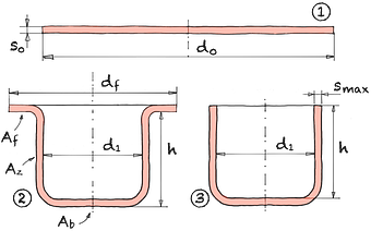
A round blank with diameter d0 is formed into a cup-shaped drawn part. The drawn part is divided into bottom area Ab , frame surface Az and, if necessary, flange surface Af. The predraw ② is also referred to as a flange draw. If the component is pulled completely through the drawing ring, this is referred to as flangeless draw ③ and the following applies: df = d1
Due to the tangential compressive stresses , the maximum sheet thickness smax is formed at the open end of the frame out of.
| Draw ratio | β0 | = | |||
| Floor space | Ab | = | % | ||
| Clear Height | h | = | mm | ||
| Max. sheet thickness | smax | = | mm |
| Blank diameter | d0 | = | mm | |||
| Diameter punch | d1 | = | mm | |||
| Flange diameter | df | = | mm | |||
| Sheet thickness | s0 | = | mm |
The draw ratio β0 is a measure of the process limit. If β0 is chosen too large ( β0 > 2), this leads to process disruptions in the form of cup base fractures.
Ab is the measure of the percentage of material stored in the soil and is higher the lower the draw ratio is.
β0 | Ab |
|---|---|
1.41 | 25 % |
2 | 50 % |
Tbl. 1 | |
| Blank diameter | d0 | = | mm |
| Clear Height | h | = | mm | |||
| Diameter punch | d1 | = | mm | |||
| Flange diameter | df | = | mm |
For drawn parts with small bottom and die radii, the blank blank diameter is calculated from the flange diameter df , the punch diameter d1 and the height of the drawn part h. If there is no flange area Af (drawing), df = d1 applies.