Degrees of deformation Deep drawing
5.1
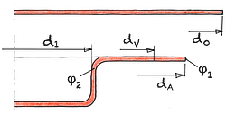
Fig. 1
Determination of the degrees of deformation φ1 and φ2
d1 diameter of punch dV comparison diameter, dA diameter of flange d0 blank diameter
If the drawn part is drawn with a remaining flange , the degree of deformation can be determined using the following procedure:
- Calculation of the degree of deformation at the outer zone dA
- Calculation of a virtual diameter dV through volume equality
- Calculation of the degree of deformation at the inner zone d1
- Substitution of dV
During the deep-drawing process, the diameter of the blank d0 is reduced to the outer diameter of the flange dA. At the same time, an inner “virtual” diameter dV is reduced to punch diameter d1. The virtual diameter dV is precisely that diameter at which a constant volume is achieved between the volume fractions from dA to dV and from d V to d1.9
The "virtual" diameter dV can therefore be determined by the following equation:
Eqn. 1
Eqn. 2
Eqn. 3
| Natural strain | φ1 | = | |||
| φ2 | = |
| Blank diameter | d0 | = | mm | |||
| Diameter flange | dA | = | mm | |||
| Diameter punch | d1 | = | mm |
Calc 1
Degrees of deformation Deep drawing 9
The following applies to the flangeless draw :
Eqn. 4
According to35 the diameter dA max , which is reached at the maximum of the drawing force , can be determined with the following equation:
Eqn. 5
Eqn. 6
| Outer edge flange max. | dA max | = | mm | ||
| Constant | C | = |
| Blank diameter | d0 | = | mm | |||
| Diameter punch | d1 | = | mm |
Calc 2
Flange diameter maximum drawing force 35
9
Siegert, K. / Blechumformung / Springer Vieweg / Berlin / 2015 / …
35
Strackerjahn, W. / Die Voraussage des Versagensfalls beim Tiefziehen rechteckiger Teile / Dissertation / Hannover / 1982 / …