Multiple draw
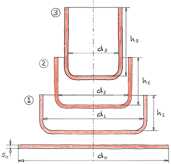
The blank diameter d0 is reduced to the final diameter dn in several deep drawings. It is important to ensure in each drawing stage that the permissible maximum draw ratio βn max is not exceeded.
The draw ratio βn is defined as the ratio of the initial circumference to the circumference of the respective drawing stage. Usually the diameters d n always refer to the inside diameter of the drawn part. The reciprocal of βn is called the drawing modulus mn.
The drawing ratios of common materials are listed in the drawing ratios table.
| Draw ratio | β0 | = | |||
| β1 | = | ||||
| β2 | = | ||||
| β3 | = | ||||
| βges | = | ||||
| Clear height | h1 | = | mm | ||
| h2 | = | mm | |||
| h3 | = | mm | |||
| h4 | = | mm |
| Blank diameter | d0 | = | mm | |||
| Diameter punch | d1 | = | mm | |||
| d2 | = | mm | ||||
| d3 | = | mm | ||||
| d4 | = | mm |
| Number | n | ≥ |
| Draw ratio | βges | = | ||||
| β1 | = | |||||
| βn | = |
A rough calculation of the required number of draw stages is given by the total draw ratio, the draw ratio of the first draw and the draw ratio of the nth draw.2738
Werkstoff | Zug 1 β0 100 | Zug 2 β1 100 |
|---|---|---|
AlMg 3 weich | 2 | 1.5 |
AlMg 3 halbhart | 2 | 1.4 |
1.4301 | 2 | 1.25 |
DC 04 | 2 | 1.3 |
Tbl. 1 Limit drawing ratios β0 β1 without intermediate annealing | ||
The limiting drawing ratio β100 refers to a punch diameter of 100 mm. If there are deviations from this diameter, this ratio must be corrected in order to correctly calculate the maximum draw ratio.8