Second draw
5.3
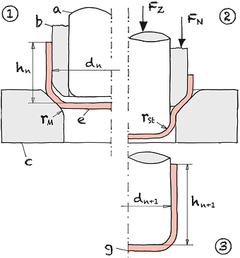
Fig. 1
Scheme second draw
① Insertion ② Forming ③ Flangeless draw a Punch b Blank holder c Drawing die dn Punch diameter e Pre-draft FN blankholderforce FZ Drawing force g Hollow body rM Die radius s0 Initial sheet thickness
The draw ratio βn is defined as the ratio of the initial circumference to the circumference of the respective drawing stage. Usually the diameters d n always refer to the inside diameter of the drawn part. The reciprocal of βn is called the drawing modulus mn.
The drawing ratios of common materials are listed in the drawing ratios table.
Eqn. 1
Eqn. 2
Eqn. 3
| Draw ratio | β0 | = | |||
| β1 | = | ||||
| β2 | = | ||||
| β3 | = | ||||
| βges | = | ||||
| Clear height | h1 | = | mm | ||
| h2 | = | mm | |||
| h3 | = | mm | |||
| h4 | = | mm |
| Blank diameter | d0 | = | mm | |||
| Diameter punch | d1 | = | mm | |||
| d2 | = | mm | ||||
| d3 | = | mm | ||||
| d4 | = | mm |
Calc 1
Multiple draw ratios Train sequence