Structure of the drawing press
11.3
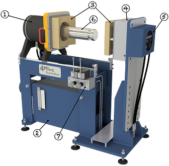
Fig. 1
Drawing press tank fitting
① Forming cylinder ② Hydraulic unit ③ Tool ④ Drawing cusion ⑤ Locking mechanism ⑥ Locking rod ⑦ Control block
The hydraulics are seamlessly integrated into the frame and the control valves are located for easy access for easy manual operation.
The forming cylinder is positioned on profile rails and can be moved effortlessly. There is a locking rod on the cylinder, which is then positively connected to the locking mechanism.
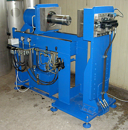
Fig. 2
Drawing press for tank fitting