Embossing height
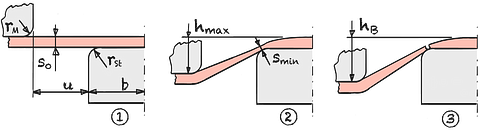
The phenomenological location of the thinnest point is at the contact point of the sheet metal with the punch radius. After a height hmax has been reached, the constriction begins.
Due to the significant reduction in the wall thickness s0 and the increasing change in the surface structure due to the formation of orange peel and micro-cracks, the maximum embossing height is defined as 85% of the fracture height.20
| Embossing height | hmax | < | mm | ||
| Minimal thickness | smin | = | mm |
| Broad | b | = | mm | |||
| Strain hardening exponent | n | = | ||||
| Punch radius | rSt | = | mm | |||
| Embossing gap | u | = | mm | |||
| Die radius | rM | = | mm | |||
| Sheet thickness | s0 | = | mm |
The maximum embossing height depends mainly on the solidification exponent and the punch radius. This equation was developed using regression calculations based on rotationally symmetrical model workpieces.20
The embossing height equation applies when the following conditions apply:
- soft unalloyed steels
- 15 ≤ b ≤ 50
- 2 ≤ rSt ≤ 20
- 2 ≤ rM ≤ 10
- 2 ≤ u ≤ 17.5
Please refer to the material table for the hardening exponents.
A comparison of different geometries has shown that lubrication has only a small influence on increasing the maximum floor height (about 7% increase with lubricant applied on both sides). By changing the geometry, however, the embossing height can be increased by up to 120%.14