Potential blank reduction
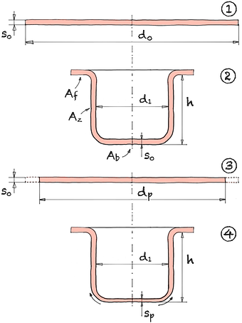
A deep-drawn part consists of the base of the drawn part, the frame and possibly a flange. The volume of the starting sheet metal, the blank, is distributed over these three surface areas due to the constant volume after forming.
A redistribution of the material from the base of the drawn part to the frame allows the size of the insert plate to be reduced while the height of the drawn part remains the same. This leads to a considerable saving of material.
| Difference sheet area | ΔAp | = | % | ||
| Difference floor area | ΔAb | = | % | ||
| Draw ratio | β0 | = | |||
| Floor space | Ab | = | % |
| Blank diameter | d0 | = | mm | |||
| Diameter punch | d1 | = | mm | |||
| Elongation thickness | εs | = | % |
Ex. I For a drawn part with an initial drawing ratio β0 of 2, the floor area is 25%. If penetration thins the floor area by 25%, it will increase by 40%. As a result, the size of the insert board can be reduced by 8.3%.
Ex. II In the case of a drawn part with an initial drawing ratio β0 of 1.41, the floor area is 50%. If penetration thins the floor area by 15%, it increases it by 17.6%. As a result, the size of the insert board can be reduced by 8.9%.
The maximum elongation εs max that can be achieved depends on the material. Common values are:
- St14 εs max = 57%
- X5CrNi189 εs max = 45.3%
- AlMg3 W19 εs max = 17.4%
- BHZ 220 εs max = 29.8%
- BHZ 300 εs max = 25.9%
- CHRX 35εsmax = 32.4%
- CHLY 40εsmax = 29.4%
- PHZ 26 εs max = 27.6%
- ZStE 260 εs max = 28.7%
- ZStE 340 εs max = 24.9%
- ZStE 420 εs max = 22.3%
- Al99.5 W7 εs max = 32.4%
- Al99.5 G9 εs max = 26.9%
- Al99.5 G13 εs max = 11.8%
- AlMg5Mn εs max = 16.2%
- AlMg3 G27 εs max = 8.5%
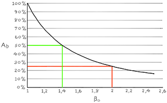
A round deep-drawn part with a diameter d1 of 100 mm and a blank diameter d0 of 200 mm has a draw ratio β0 of 2. In this case, the percentage of the area originally contained in the plate that is now stored in the base of the drawn part is 25 %. However, if the draw ratio β0 is 1.41, then 50% of the surface area originally contained in the plate is in the bottom of the drawn part.