Modern drawing cusion & gears
Drawing cusion are used to apply the necessary blank holder force to the sheet metal, which in turn affects friction. Depending on the shape of the drawn part, a certain minimum surface pressure is required to prevent wrinkling. However, excessive adjustment of the blank holder force can cause cracks in the material.
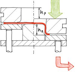
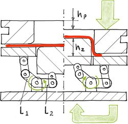
The blank holder is supported by drawing pins. The press stroke hP under load corresponds to the drawn part height hZ. By displacing the oil via a control edge, the energy of the blank holder is converted into heat, which has to be removed from the hydraulic circuit in a laborious process. Therefore, the energy of the blank holder is to be booked as energy loss.
In many cases, the blank holder force is kept constant over the drawing stroke. This leads to a high mean value of 0.95. As a result, the work of the blank holder is often higher than the work of the punch.
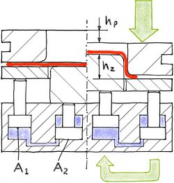
The downward movement of the press ram is converted into an upward movement of the drawing punch through a communicating tube. The press stroke hP depends on the selected transmission ratio A2 / A1 half of the drawn part stroke, which halves the press work. By doubling the drawing speed, production output is doubled.69
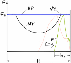
The force-displacement curve is compressed by the transmission ratio. This enables the production of high drawn parts on mechanical presses that were previously unsuitable for this type of press. Since the transmission ratio of the gearbox can be freely selected, the force-displacement curve can be adapted to the press used.
In comparison to single-acting deep-drawing with displacement cushions, the use of energy is reduced by half, which means that the working capacity of the press is used more efficiently.
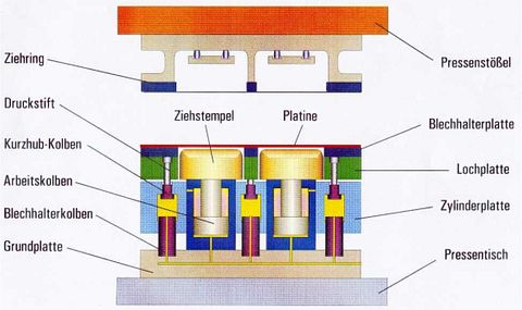
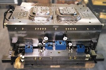
Modern hydraulic pressure compensators are designed in a monoblock design. They offer efficient power transmission and even load distribution over the entire holding area, which is particularly important for complex drawn parts.
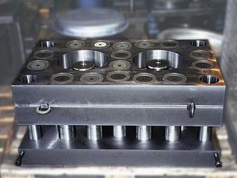
The valve control can be positioned on the base plate. The blank holder force can be variably adjusted by means of an additional displacement control.
The translating properties of the pressure compensator can also be achieved using a mechanical lever. The gear ratio is determined by the lever lengths L1 and L2. An advantage of this method over the hydraulic pressure compensator is the higher rigidity, which makes this system more suitable for higher speeds and larger quantities.2
In addition to taking efficiency into account, it is important to compare the achievable volume outputs when assessing the economic viability of presses.
Due to the advance travel required during deep drawing, the output of hydraulic presses is significantly lower than that of mechanical presses. With deep draws of up to 250 mm drawing depth, outputs of 5 to 10 1/min can be achieved.
On the other hand, deep pulls on mechanical presses can only be achieved with a transmission gear due to the force-distance curve. With hydraulic gearboxes, drawing depths of 250 mm and outputs of 20 1/min can be achieved successfully.