Die radius
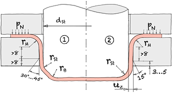
When passing through die radius rM , the sheet experiences tangential pressure due to the reduction in diameter. These compressive stresses are superimposed by indirect tensile stresses, which are transferred by the drawing die over the edge into the forming area. An oversized die radius can cause wrinkles in the material.
In addition, the sheet metal bends and bends back as it passes through. die radius creates areas with varying contact normal stresses.
A drawing die radius that is too narrow can disrupt the flow of the sheet material, which can lead to cracks in the bottom area.
| Die radius | rM | = | mm |
| Constant | C | = | ||||
| Sheet thickness | s0 | = | mm |
| Die radius redrawings | rM n | = | mm |
| Constant | C | = | ||||
| Die radius preferred | rM n-1 | = | mm |
According to Oehler* if the radius of the drawing edge is too small, this leads to cup base fractures. Excessively large die radii facilitate undesired wrinkling, which leads to jamming in the clearance, flattened wrinkles and frame fractures in the frame.
| Die radius | rM | = | mm |
| Blank diameter | d0 | = | mm | |||
| Diameter punch | d1 | = | mm | |||
| Limiting drawing ratio | β100 | = | ||||
| Sheet thickness | s0 | = | mm |
The empirically determined factors of 0.04 and 50 are based on the experience that the rework required for tools with short tool lives due to abrasion, scratches and adhesion leads to a continuous increase in rM.
The following rule applies here: 5 < rM / s0 < 10 because according to the bending component from rM / s0 > 5 there is no reduction in sheet thickness and at rM / s0 < 10 there is no longer any lifting of the sheet from the drawing edge under the effect of tangential compression stresses.
This is often related to insufficient blank holder pressure or blank holder deflection. Deflection of the press table and clamping elements leads to compression wrinkles and rapid tool wear.
Drawing edge radii that are too large cannot be reduced. Drawing edge radii that are too small, whether intentional or unintentional, are increasing. An intended tool life increase through surface treatment and coating processes must specifically cover this area without errors.*
| Die radius | rM | = | mm |
| Blank diameter | d0 | = | mm | |||
| Diameter punch | d1 | = | mm | |||
| Sheet thickness | s0 | = | mm |
Between the optimal There is a quadratic relationship die radius and the sheet thickness.* The sheet thickness has a significant influence on the bending force. There is also a quadratic relationship between the bending force at die radius and the sheet thickness.
| Optimum die radius | rM opt | = | mm |
| Coefficient of friction | μ | = | ||||
| Yield strength | Rp 0,2 | = | MPa | |||
| Sheet thickness | s0 | = | mm |
This relationship applies to:
- Sheet steel DC04, DC04ZE, ZstE340ZE, ZstE250i, Zst300BH
- Aluminum sheet AA5182-0, AA6009-T4, AA6016-T4
With the properties:
- μ = 0.02 … 0.15
- s0 = 0.7...1.5
- RP 0.2 = 150 … 350 MPa
Material parameters eg from the table for sample materials.
Friction values see table of friction values or friction & tribology.
| Max. die radius aluminium | rM max Alu | ≤ | mm |
| Sheet thickness | s0 | = | mm |
| Die radius | rM | = | mm |
| Constant | C | = | ||||
| Blank diameter | d0 | = | mm | |||
| Diameter punch | d1 | = | mm | |||
| Sheet thickness | s0 | = | mm |
The values determined in this way can be reduced by 20% after* if
- the drawn part retains a flange or
- the draw ratio β1 <1.4