U-Bending & Die Stamping
16.5
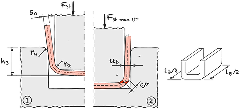
Fig. 1
U-bending*
lB Bending length εa Elongation of outer fiber FSt Punch force F St max UT Maximum punch force Bottom dead center rM Die radius rSt Punch radius ub Bending gap s0 Wall thickness
The conditions for U-die bending correspond to free bending with twice the bending length b. At bottom dead center (BDC), the punch hits hard and the process switches to stamping. A higher embossing force FSt max UT is then required to ensure the flatness of the workpiece base.
Eqn. 1
Eqn. 2
Eqn. 3
Eqn. 4
Eqn. 5
Eqn. 6
Eqn. 7
| Max. punch force | FSt max | = | kN | ||
| Maximum punch force UT | FSt max UT | > | kN | ||
| Coefficient | ξ | = | |||
| Medium natural strain | φm | = | |||
| Bending factor | c | = | |||
| Bending work | WB | = | J |
| Die radius | rM | = | mm | |||
| Punch radius | rSt | = | mm | |||
| Sheet thickness | s0 | = | mm | |||
| Bending gap | ub | = | mm | |||
| Bending length | lB | = | mm | |||
| Average work hardening | kfm | = | MPa | |||
| Coefficient of friction | μ | = | ||||
| Mean factor bending | mB | = | ||||
| Bend height | hB | = | mm |
Calc 1
U-Bending & Die Stamping
The tensile strength Rm can be used as an approximation for kfm.
By using a flow curve and the mean degree of deformation φm
more precise values for kfm can be determined.
*
Kluge, Siegfried / Prozesse der Blechumformung / Carl Hanser Verlag / München / 2020 / …