Drawing punch Partial forces and total force
5.2.2
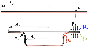
Fig. 1
Designations deep drawing
dA Flange diameter d0 blank diameter d1 punch diameter h drawn part height pn blank holder blankholder pressure s0 wall thickness rM drawing ring radius μ1 coefficient of friction of friction sheet metal / blankholder μ2 coefficient of friction of friction sheet metal / drawing die μ3 coefficient of friction of friction sheet metal / drawing ring radius
When deep-drawing rotationally symmetrical sheet metal parts, five partial forces act on the drawing predraw :
- Fidis the ideal forming force required for lossless forming in the forming zone.
- Fb the bending force required to bend the sheet around die radius rM.
- FRB/N is the frictional force acting between the sheet metal and the blankholder.
- FRB/Z is the frictional force acting between the sheet metal and the drawing die.
- FRB/ZR is the frictional force acting between the sheet metal and the rounding of the die rM.
Eqn. 1
Eqn. 2
Eqn. 3
Eqn. 4
Eqn. 5
Eqn. 6
Eqn. 7
| Total force punch | Fges | = | kN | ||
| Tensile stress | σZ | = | MPa | ||
| Ideal forming force | Fid | = | kN | ||
| Bending force | Fb | = | kN | ||
| Friction force blank to blankholder | FR B/N | = | kN | ||
| Friction force blank to drawring | FR B/Z | = | kN | ||
| Friction force die radius | FR B/ZR | = | kN |
| Diameter flange | dA | = | mm | |||
| Diameter punch | d1 | = | mm | |||
| Sheet thickness | s0 | = | mm | |||
| Average work hardening | kfm | = | MPa | |||
| Superior yield stress | kfi | = | MPa | |||
| Die radius | rM | = | mm | |||
| Blankholder Pressur | pn | = | MPa | |||
| Coefficient of friction | μ1 | = | ||||
| μ2 | = | |||||
| μ3 | = |
Calc 1
Partial forces according to Siebel and Panknin935
The coefficients of friction can vary depending on the surface properties of the tool and the sheet metal.
The average work hardening kfm and the superior yield stress kfi are calculated using the deformation limits φ1 and φ2 and using the flow curves. The natural strain φ2 should be used for kfi.
An estimation of the maximum total force on the punch can be made using the following simplification:
Eqn. 8
9
Siegert, K. / Blechumformung / Springer Vieweg / Berlin / 2015 / …
35
Strackerjahn, W. / Die Voraussage des Versagensfalls beim Tiefziehen rechteckiger Teile / Dissertation / Hannover / 1982 / …