Bending force III
16.7.3
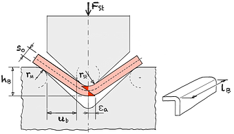
Fig. 1
V-Bending21
lB Bending length εa Elongation of outer fiber FSt Punch force rM Die radius rSt Punch radius ub Bending gap s0 Wall thickness
Eqn. 1
Eqn. 2
Eqn. 3
Eqn. 4
Eqn. 5
Eqn. 6
| Max. punch force | FSt max | = | kN | ||
| Maximum punch force UT | FSt max UT | > | kN | ||
| Coefficient | ξ | = | |||
| Medium natural strain | φm | = | |||
| Bending factor | c | = | |||
| Bending work | WB | = | J |
| Die radius | rM | = | mm | |||
| Punch radius | rSt | = | mm | |||
| Sheet thickness | s0 | = | mm | |||
| Bending gap | ub | = | mm | |||
| Bending length | lB | = | mm | |||
| Average work hardening | kfm | = | MPa | |||
| Coefficient of friction | μ | = | ||||
| Mean factor bending | mB | = | ||||
| Bend height | hB | = | mm |
Calc 1
Maximum force FSt max according to Kluge21
For kfm, the tensile strength Rm can be used as an approximation.
By using a flow curve and the average degree of deformation φm
more precise values for kfm can be determined.
To reduce spring back , the die must sit hard. The maximum punch force FSt max should be multiplied by a factor greater than 2.
The coefficient of friction table for sheet metal forming should be used as the friction value μ.
21
Kluge, Siegfried / Prozesse der Blechumformung / Carl Hanser Verlag / München / 2020 / …